CUAV 24GHz Miniature UAV Drone Altimeter Radar ISTRA24 Obstacle Avoidance Radar
CUAV 24GHz Miniature UAV Drone Altimeter Radar ISTRA24 Obstacle Avoidance Radar is backordered and will ship as soon as it is back in stock.
Couldn't load pickup availability
US Shipping Notice
US Shipping Notice
Due to the new tarrif policy, if you choose the following shipping method to US:
Express Shipping: Plese provide your Fedex Account.
DHL: Please provide your EIN or SSN number.
Tarrif bill will send to these account.

CUAV 24GHz Miniature UAV Drone Altimeter Radar ISTRA24 Obstacle Avo...
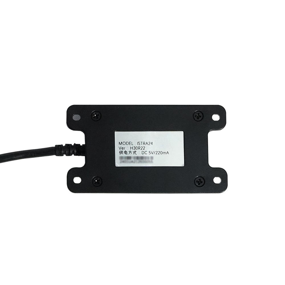
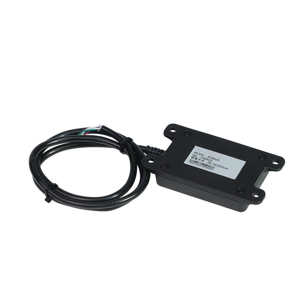
CUAV24GHz Miniature UAV Altimeter Radar ISTRA24
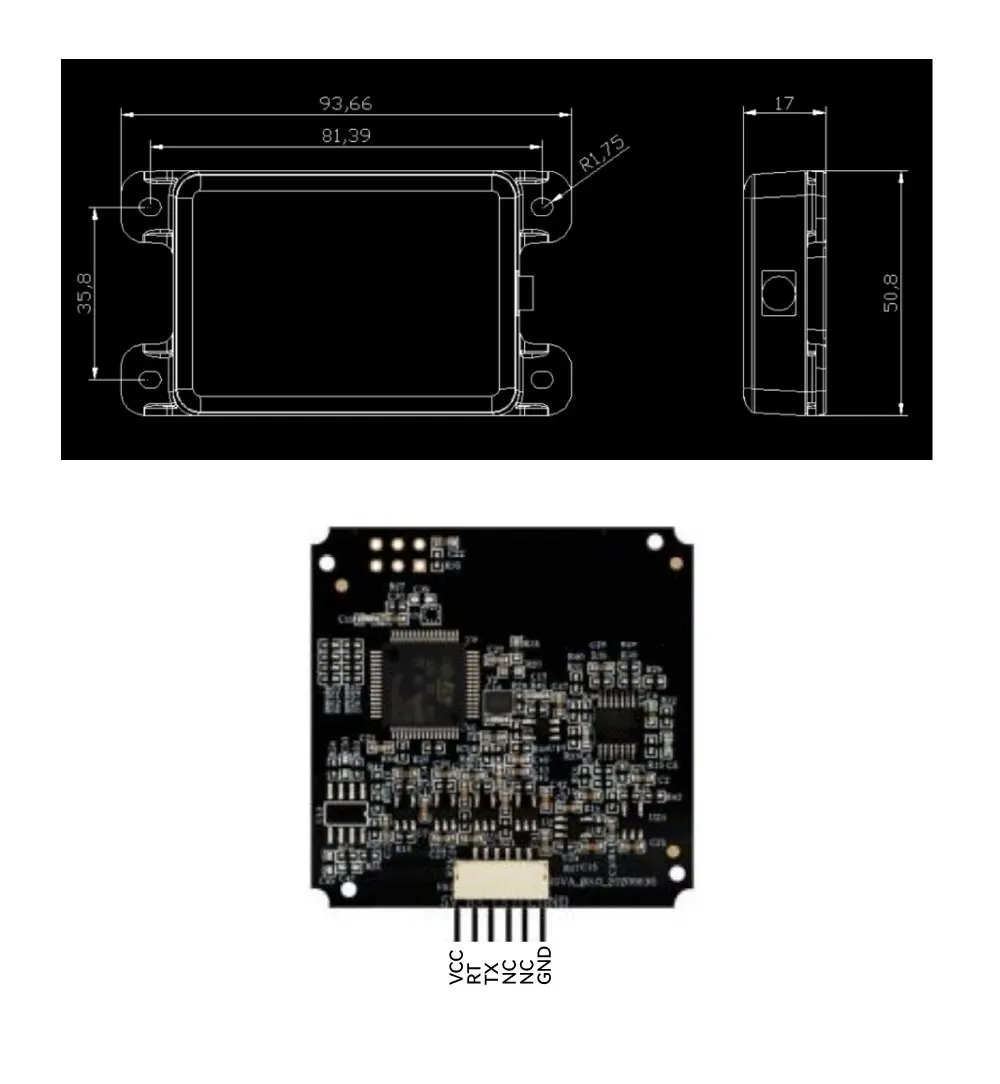
The 24GHz Miniature UAV Altimeter Radar (ISTRA24) has the PCBA size as little as 45*45mm and the weight of 6.5g, which is very convenient for being integrated to body of UAV body or under the arms of the machine.
(ISTRA24) has a PCBA size of as little as 45*45mm and a weight of 6.5g, which is very convenient for being integrated into the body of the UAV body or under the arms of the machine.
An original antenna design. the signal processing algorithm of super-high efficiency and the comprehensive real-time signal processing method of high sensitivity based on the time domain, frequency domain, and phase positions to greatly reduce the physical size of radar modules, making it convenient to integrate the radar model into the body of UAV and bringing in a brand new probability for the UAV industry. this millimeter-wave-altimeter radar can realize altitude measurement in the range of 0.2 ~ 50m (it is not suggested hovering for a long time under the altitude of 0.5m), which provides a remarkably convenient feature for hovering or flying at a constant distance to the ground by UAV.
The constant altitude mode is the most important one among the fly controlling modes of UAVs, while the altimeter radar of high accuracy is the basis for flying steadily under the constant altitude mode. As we all know, in order to make sure the lift force and weight balance, the drone drivers shall pay a lot of attention on slight adjustment operation, while the altitude fixed mode of UAV with the help of altimeter radar may decrease the operation difficulty faced by the drone driver. After entering the alti-tude-fixed mode, it is possible for the drone driver to control the flying directions of the UAV without to balance the lift force, relieving the drone driver greatly and decrease the explosion risks. Furthermore,possible to achieve a better photographing effect when hovering at high altitude with the help of the altimeter radar. What’s more, the altimeter radar is helpful for ensuring steady flying with a constant distance to the ground, increasing the applicability of UAV in specific application scenes including line patrol.
Specification:
System Features
Transmitting frequency:24.0~24.25GHz
Transmitting power(EIRP): 20dBm
System: Frequency Modulated Continuous Wave
Hardware interface: UART-TTL
Dimension:45*45*6mm(PCBA)
Weight: 6.5g
Working voltage: 4~5.5V Typical value: 5V (please make use of an independent power supply to power up)
Working current:200~275mA Typicalvalue:220mA@5V
Storage temperature:-40~85C
Working Temperature:-40~80C
Ranging Features
Altitude-fixing range:0.2m~50m
Update rate:50Hz
Aerial Features
Degree of the transmitting antenna’s tilt angle: 20°
Width of the receiving antenna’s tilt angle: 31°
Width of the transmitting antenna’s azimuthal angle: 31°
Width of the receiving antenna’s azimuthal angle: 20°
Electrical level of the transmitting antenna’s sidelobe -19dB
Electrical level of the receiving antenna’s sidelobe -19dB
Package Includes:
1x CUAV 24GHz Miniature UAV Drone Altimeter Radar ISTRA24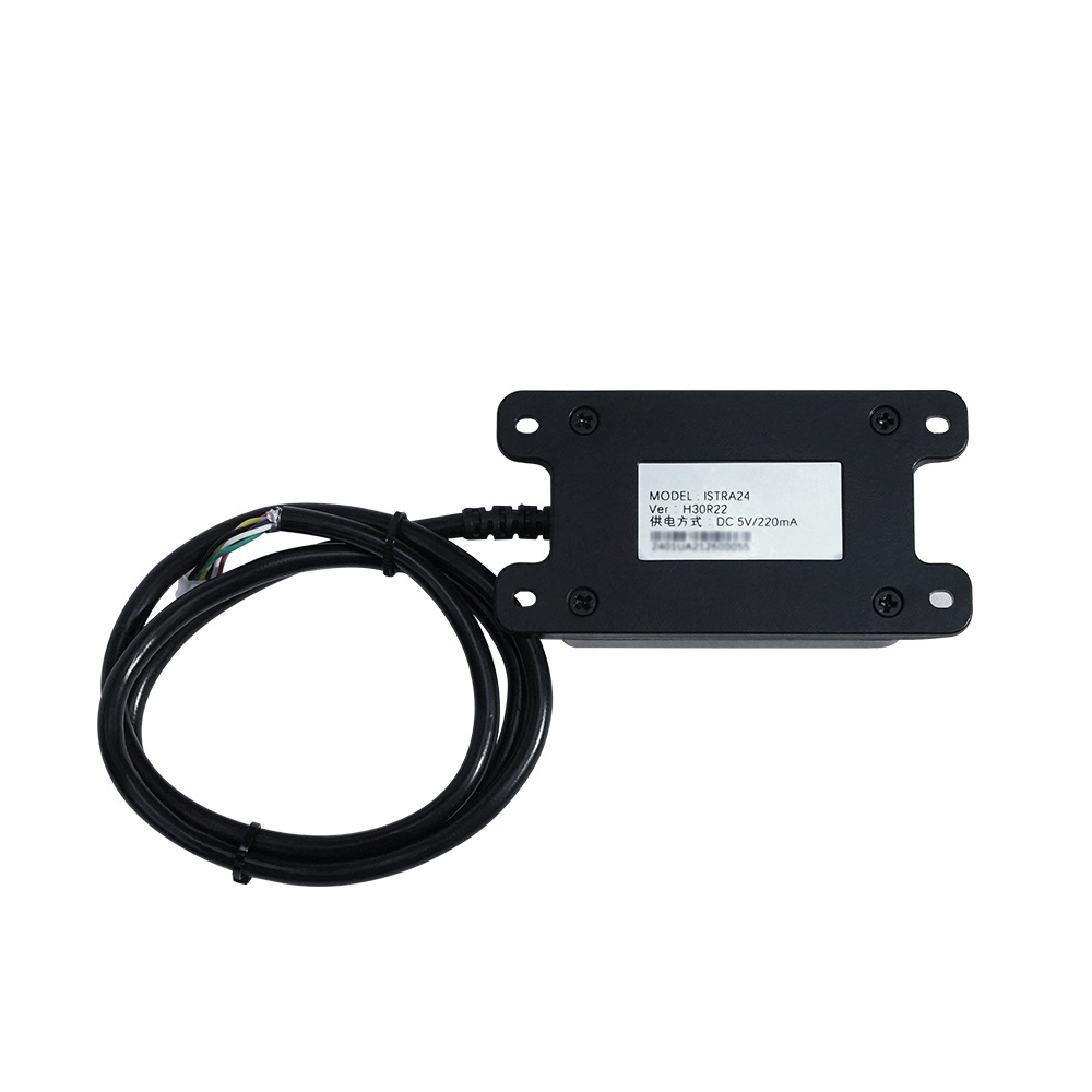
The test method is as follows: The latest ground station software may be downloaded and installed from the website of Ardupilot (such as 1.3.74 Mission Planner ).https://firmware.ardupilot.org/Tools/MissionPlanner/ The tools or software that may be used for testing are as follows: • ISTRA24 Miniature Altimeter Radar • Laptop/PC • Independent power supply system (5V) • The software a Mission planner • The open-sourcing flying controller (the hardware missed may be downloaded from the website of Ardupilot). • USB connection lead/ radio station for data transmission ISTRA24 Miniature Altimeter Radar connects the open-source flying controller and power input unit (it is not allowed to power up the radar model directly by the flying controller power supply system, please make sure to adopt an independent power supply system). Start the software Mission Planner at the ground station and connect the flying controllers (USB connection lead/ radio station for data transmission) Software running steps are as follows: “configuration/debugging”-“table of all parameters” and set up the following parameters: • EK2 ALT SOURCE-1 • RNGFND1 TYPE-8 • RNGFND1 ORIENT=25 • SER1 BAUD=115200(other SER interfaces may also be selected.) • SER1 PROTOCOL-9 The operations after configuration are as follows: • Click “flying data” and return to the main interface • Double click the site circled by the red box in Figure 3 and export the interface “Display This” as shown in Figure 3, cancel other selections with “sonar range” being the only one being chosen, which will display “distance of sonar”, indicating the